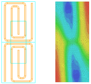
IC-Tempering: Layout of a heating plate
During the operating test of ICs, the temperature should be kept as constant as possible. For this purpose, the ICs are thermally contacted to a heating plate, which is flown by air with adjustable inlet temperature.
Before building up a first prototype, an optimum design of the flow channels within the heating plate should be determined by simulation. The thermal analysis gives information on the achievable homogeneity, controllability and inertia of the system.
From the simulations, the optimum section of the flow channels with respect to temperature homogeneity could be derived. The optimum result for temperature homogeneity is applying both halves of the heating plate with independent helical flow channels (see top figure).
If the plate is equally loaded with 10 [W], the difference between minimum and maximum temperature on the plate is less than 0.1 [K] (top figure).
If this heat load is only applied to the inner or outer region of the plate, this difference increases to 0.4 [K] or 0.2 [K], respectively (center figure).
Further improvement of the homogeneity would require separate flow channels with independently controlled inlet temperatures for each region.
Finally, the simulation gives information about the time behavior of the heating plate. As an example, the temperature of the plate should be changed from +120 [°C] to -60 [°C]. For this purpose, the plate is flown with air at -120 [°C].
The bottom figure shows the temperature behavior at several positions on the heating plate. The nominal temperature is achieved after about 20 [min]. Afterwards the temperature of the plate further decreases, because in this case the inlet temperature of the air is not controlled.
Our specialists are always at your disposal to flexibly respond to your respective requirements and wishes.
Dr. Michael Elbs, Managing Director

Temperature distribution for homogeneous load (ΔT=0.1 [K])
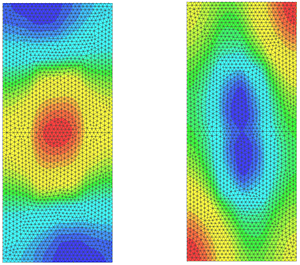
Temperature distribution for inhomogeneous heat load inside (left ΔT=0.4 [K]) and outside (right ΔT=0.2 [K])
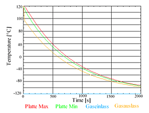
Temperature behavior during cooling down